


1959 PASSENGER CAR DIRECTION SIGNALS


These mini- techs are being taken from GM's Chevrolet Service News. The Service News publication was provided by GM each month to its service departments. Each month this publication covered persistent problems that service departments might be facing, and provided information on how to fix the problem.
These Chevrolet Service News publications by no means covered all the problems a service department faced with the introduction of each new years models. Likewise our seven mini-techs will by no means answer all the problems.
Your best source for information on repairs and restoration are the Shop Manuals and Assembly Manuals for your year Chevy without these publications you will be working in the dark!
1959 PASSENGER CAR DIRECTION SIGNALS
The most prevalent causes of 1959 passenger car direction signal ma/function are listed below, along with recommended correction for each.
Trouble: Canceling prong on steering wheel will not cancel the control lever.
Correction: Remove steering wheel and bend canceling prong on wheel assembly so that it stands perpendicular to the hub of the wheel. Do not "over bend" the prong as this will lead to an objectionable clicking sound when the turn signal lever is in the neutral position. Use care in replacing the wheel so that the prongs do not strike the steering shaft on assembly.
Trouble: Turn signal will not cancel, usually only in one direction.
Correction: Some early production canceling pawls, Part No.5950164, were distorted in manufacture, causing the pawl to remain clear of the canceling prong on the steering wheel when moved into a turn position. Replacement of the pawl is the best fix.
Trouble: Turn signal canceling is erratic and may or may not cancel on turns in either direction.
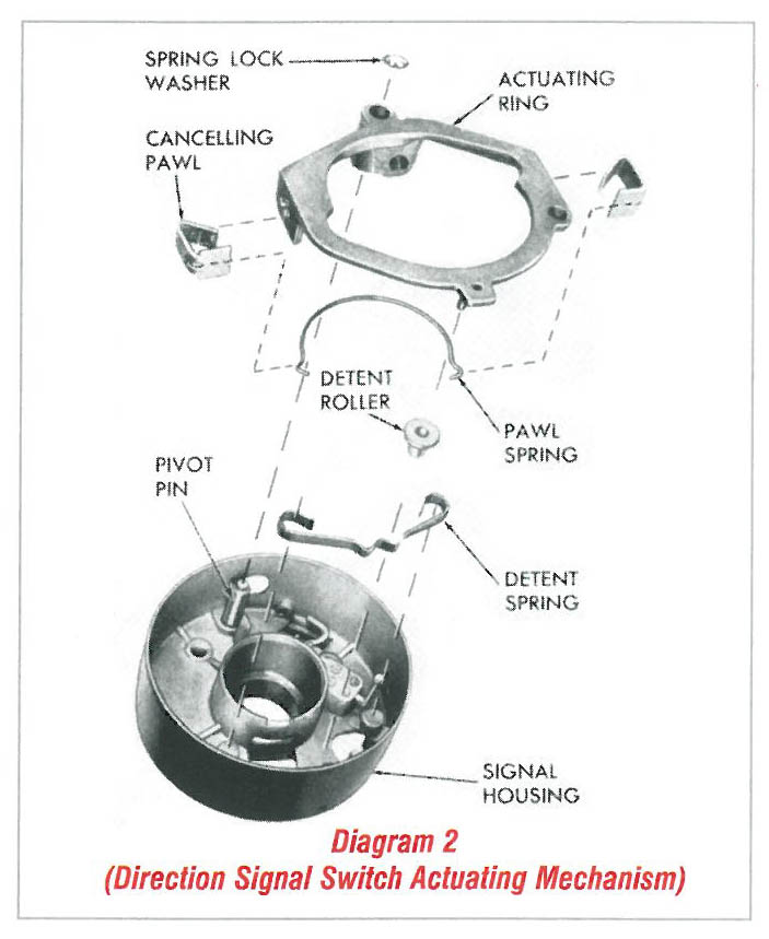
Correction: This condition is usually due to the actuating ring pivot pin becoming loose in the housing. The pin is a press fit in the housing and if it loosens, the actuating ring is free to move out of the path of the canceling cam prongs. If the pin is loose in the housing, it should be removed and the serrations raised slightly. This may be done by striking the serrations several times using a light hammer and small chisel. The pin should then be pressed into the housing to a depth that locates the washer shoulder on the pin 1/32" above the top surface of the actuating ring.
Trouble: Horn blows on turns while direction signals are operating.
Correction: This could be the result of interference between a turn signal canceling pawl and the horn connector assembly (spring loaded horn contact), which would ground the horn circuit. Pawl interference is probably caused by the actuating ring pivot pin either being loose, or pressed too shallow in the signal housing-correction explained earlier. If pressing the pivot pin to specified depth does not stop horn blowing, it will be necessary to lightly grind the top of the offending pawl to obtain clearance.
Trouble: Flashing and canceling of lights is erratic.
Correction: This condition usually results from the turn signal switch either being damaged or out of adjustment and can be eliminated by performing the checks and adjustments outlined below:
- 1. Remove screws holding switch case to mast jacket.
- 2. Remove control wire from spring clip on switch sliding contact.
- 3. With the electrical lead still connected to the switch, check travel of switch slide to assure that slide movement is unrestricted. If slide action is restricted it may be caused by the female electrical connector forcing a loose switch terminal blade against the slider. When this condition occurs, the switch assembly must be replaced.
- 4. Before installing the switch, move switch slide to a dimension of 9/16 inch, measured from lower end of switch case to lower edge of slide clip. (This positions the slider at center of the dead band on the switch and divides lost motion occurring in the signal control assembly).
- 5. Place signal control lever in neutral detent and without moving sliding contact, install control wire into slide clip. Note:-When installing wire to clip do not bend Bowden cable as this will change relation of wire in final installed position.
- 6. Use care in remounting switch to mast jacket to prevent switch case being moved in relation to slide, as this would disturb neutral setting.